ASME B31.3 · API 582 · AWS D1.1 Certified Field Crew
WEATHER SHIELD~45°C ambient
CERAMIC FIBER BLANKET — 2400°F RATED50mm thick
TC1TC2TC3TC4TC5THERMOCOUPLE ARRAY — 5-POINT COVERAGE1204°C hold
HAZHAZWELD BEADE7018 filler
1.5" wallBASE METAL — API 5L X65P91 Cr-Mo
1204°C
Soak Temperature

Every layer documented. Every degree recorded.

Anneal deploys field-certified PWHT crews to pipeline tie-ins, refinery turnarounds, and structural connections — wrapping every joint, placing every thermocouple, and delivering a PE-stamped report before your inspector leaves the gate.

12,000+
Joints Completed
14-Day
Turnaround Windows
100%
Documentation Rate
0
Failed Inspections
Live Recorder● Recording
SOAK0h8h
Ramp 150°F/hr1204°C / 1h hold
Scroll
The Controlled Ramp

Five stages.
Five artifacts.

Every PWHT job follows the same controlled sequence. We show you the artifact from each stage — not because we have to, but because it's the only way to prove the work was done right.

01
Mobilization

Thermocouple Mapping

Our crew arrives with calibrated Type-K thermocouples, attachment hardware, and a joint-specific layout sketch pre-drawn from your isometric. Every TC placement is documented before the blanket goes on.

TC placement per AWS D10.10Weld map cross-referenceInspector sign-off
AmbientMobilization target
TC Layout SketchMobilization
TC1TC2TC3TC4TC5360° circumferential coverage

Delivered to QC before heat-up

02
Ramp Programming

Controller Setup & Ramp Rate

The heat treatment controller is programmed with your code-specified ramp rate — typically 150–300°F/hr for carbon steel, custom for P91 and chrome-moly. The program is printed and attached to the job package before energizing.

ASME B31.3 Table 331.1.1Customer spec override acceptedDigital + paper record
150°F/hrRamp Programming target
Ramp Program PrintoutRamp Programming
0h4h1204°C150°F/hr programmed ramp

Signed by crew lead, filed to job package

03
Soak Hold

Temperature Hold Monitoring

All five thermocouples must reach and hold the specified soak temperature within the tolerance band — typically ±25°F. The recorder runs continuously. If any TC falls out of band, the hold timer resets automatically.

±25°F band enforcementAuto-reset on band exceedanceContinuous recorder trace
1204°C holdSoak Hold target
Hold-Time CertificateSoak Hold
HOLD-TIME CERTIFICATEJoint ID:P-101-W-047Soak Temp:1204°C ± 14°CHold Duration:60 min (met)All TC In Band:✓ YesSigned: J. Harrington, PWHT Tech Level II

Signed by Level II PWHT technician

04
Controlled Cooldown

Cooldown Slope Overlay

Cooldown is not passive. The controller manages descent rate per code — 300°F/hr maximum for most P-numbers — until the joint reaches 600°F, at which point the blanket is removed and air cooling completes the cycle.

Code-controlled descent600°F blanket-off thresholdDeviation auto-flagged
300°F/hr maxControlled Cooldown target
Cooldown Slope OverlayControlled Cooldown
Code limitActual1204°C600°F

Overlaid on recorder chart, deviation-flagged

05
Documentation Delivery

PE-Stamped PWHT Report

Within 24 hours of cooldown, you receive the complete PWHT package: the recorder chart with all TC traces, the hold-time certificate, the cooldown overlay, the TC layout sketch, and the final report with PE stamp — ready for your code inspector.

PE stampAll TC tracesHold certificateCooldown chartWeld map reference
ReportDocumentation Delivery target
Complete PWHT ReportDocumentation Delivery
POST-WELD HEAT TREATMENT REPORTProject:Midland Basin Tie-In — Sta. 42+150Joint Count:14 joints completedCode:ASME B31.4 / API 1104Cert. Eng.:PE #TX-48291Status:✓ ACCEPTEDPESTAMP

PE-stamped, inspector-ready, 24hr delivery

Engineering Review

Download a real
PWHT report.

Before you recommend a PWHT contractor to procurement, you need to see the documentation. This is an unredacted report from a 2024 pipeline tie-in — full recorder traces, thermocouple layout, hold certificate, cooldown overlay, and PE stamp.

All 5 thermocouple traces overlaid
Hold-time certificate with band data
Cooldown slope vs. code limit
PE stamp, TX license #TX-48291
Ready to submit to your code inspector

Get the sample report

Engineering access only — no sales follow-up.

PDF · 12 pages · No login required

What We Heat Treat

Four project types.
One documentation standard.
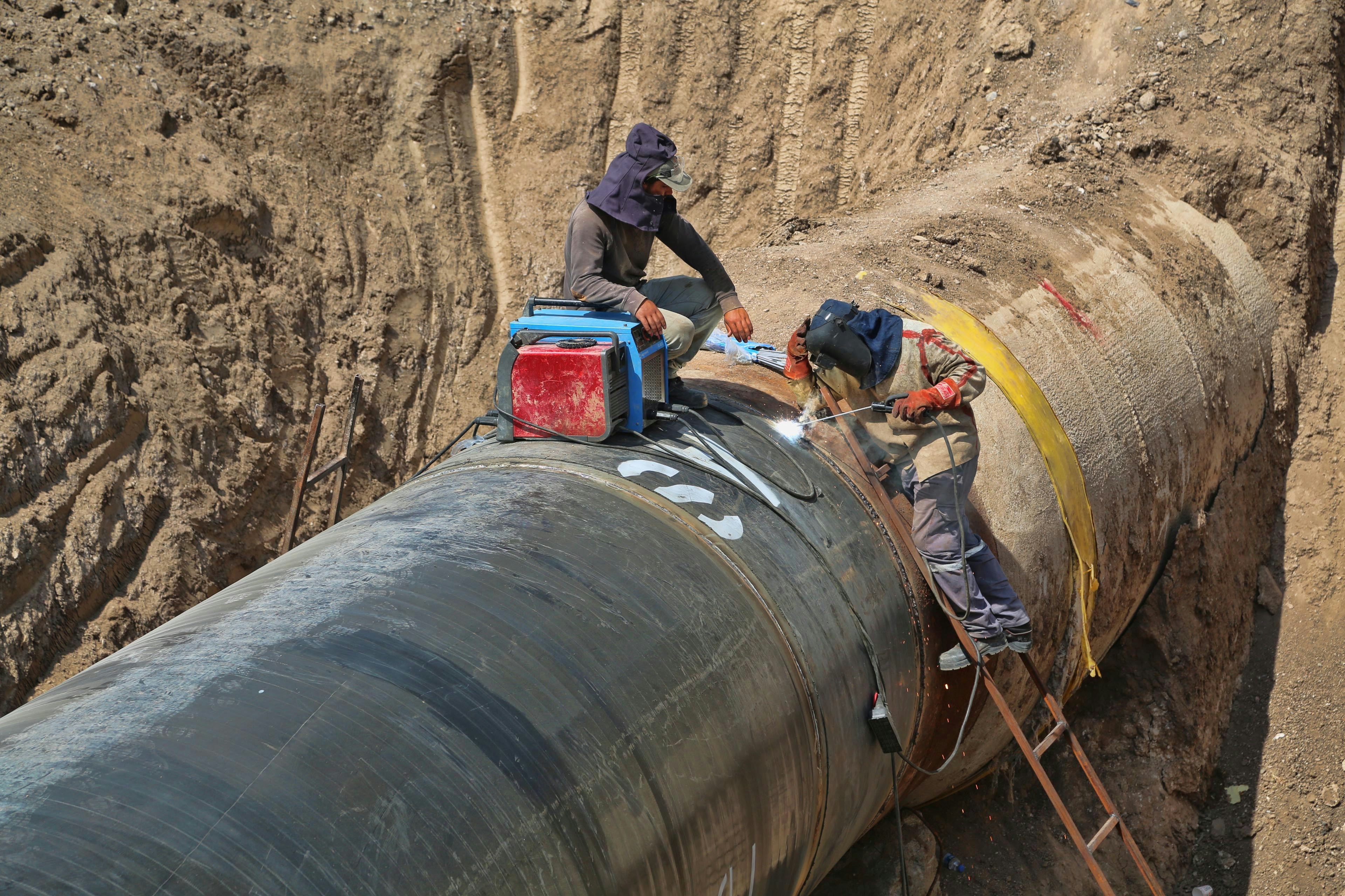
Whether you're closing a DOT-regulated mainline or qualifying a pressure vessel weld for NBIC inspection, the report you receive looks the same: complete, stamped, and ready for your code inspector.

Pipeline construction workers welding a large diameter pipe joint in open field
8,400+
Pipeline joints
DOT-regulated mainline connections

Pipeline Tie-Ins

We mobilize to remote right-of-way within 48 hours. Every tie-in joint gets a dedicated thermocouple layout, a controller program matched to your P-number, and a PWHT report your DOT inspector will accept on first submission.

API 5L X52–X80ASME B31.4 / B31.8DOT Part 192/19548-hr mobilization
Refinery piping network with complex pipe connections and industrial equipment at dusk
14-Day
Turnaround windows
14-day windows, 100+ joints

Refinery Turnarounds

Turnaround schedules don't flex. We staff multiple controller crews, run parallel joints simultaneously, and deliver documentation daily so your QC team never waits on paperwork to close a joint.

ASME B31.3 ProcessP91 / P22 Cr-MoParallel crew capabilityDaily doc delivery
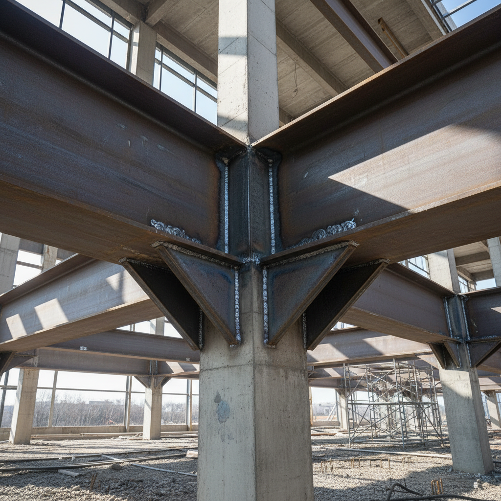
Steel structural beam connection with visible weld joints on a construction site
1.5"
Wall thickness handled
Heavy wall, high-consequence

Structural Connections

When a structural engineer specifies PWHT on a heavy wall connection, residual stress is the concern. We place thermocouples at the weld toe, not just the crown, and hold the soak until all points confirm.

AWS D1.1 / D1.5Heavy wall ≥1.5"Weld toe TC placementResidual stress protocol
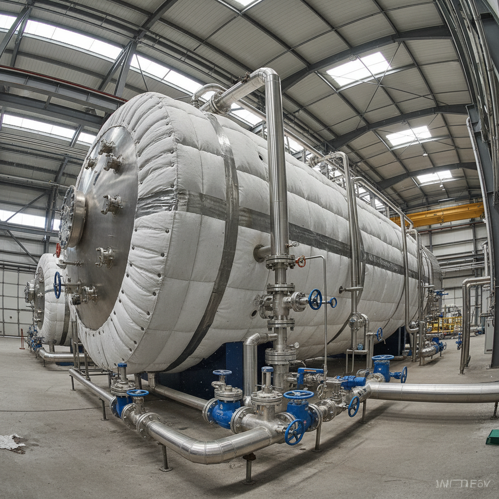
Industrial pressure vessel with insulation wrapping and pipe connections at a chemical plant
100%
NBIC compliant
ASME Section VIII shop & field

Pressure Vessels

Pressure vessel PWHT demands uniform temperature across the entire shell, not just the weld seam. We use extended thermocouple arrays and overlap the heated zone by code-minimum distances on all sides.

ASME Sec. VIII Div. 1UCS-56 table complianceShell + nozzle zonesNBIC documentation
Start a Job

Send us your
weld map.

Upload your isometric or weld map and we'll return a thermocouple layout sketch and mobilization estimate within one business day — before any PO is signed.

Drop your isometric or weld map here

PDF, DWG, DXF, or image — max 25MB

We'll return a TC layout sketch and mobilization estimate within one business day. No PO required.

Direct Line

(432) 555-0178

Mon–Fri 6AM–6PM CT

Email

ops@anneal-pwht.com

Response within 4 hours

Service Area

Permian Basin & Gulf Coast

Nationwide mobilization available